I’m a graduate student at NYU studying mechanical engineering, with a passion
for aerodynamics, aerospace, and anything that requires CFD.
M.S. Mechanical Engineering, NYU Tandon, expected May 2028
B.S. Mechanical Engineering, Binghamton University
Simulations Team Lead, AeroBing Rocketry, 2025 - 2026
It started with a love for Star Wars, F1, and sandbox video games like Garry’s Mod
and LittleBigPlanet. Each in its own way technically complex, creative, and design and
prototyping oriented.
As I got to college, I learned what simulations actually were. Yet to me they scratched
that itch as if it was a video game. CFD and FEA feel like a sandbox version of the real
world: build the thing, run it, test and upgrade it based on the results. Different UI,
of course, but the same childlike curiosity to see if a structure would still hold at
Mach 5, or how badly it would deform under 50 gigapascals.
The work changed a bit, but stayed around creating a good workflow where the setup was
careful enough that the answer means something.
400 × 400 mField site surveyed with drones, ground-penetrating radar and LiDAR
3 profilesHydrokinetic turbine blades, compared three at a time
450 µmMicrochannel where the flow never leaves laminar and the geometry has to do all the mixing
Mach 3Launch vehicle
Most of that has been in ANSYS Fluent, with stretches in MOOSE for finite element
multiphysics and OpenFOAM alongside it. The habit that runs through all of it is
checking the solver against something else.
Each simulation and the independent method it was checked against
Micromixer
Published literature
Turbines
Blade element theory
Senior design structure
Hand calculations
Rocket
RASAero II
A number that only one method produced is a number I do not trust yet.
B.S. in Mechanical Engineering from Binghamton in May 2026, and starting the M.S. at
NYU Tandon this fall.
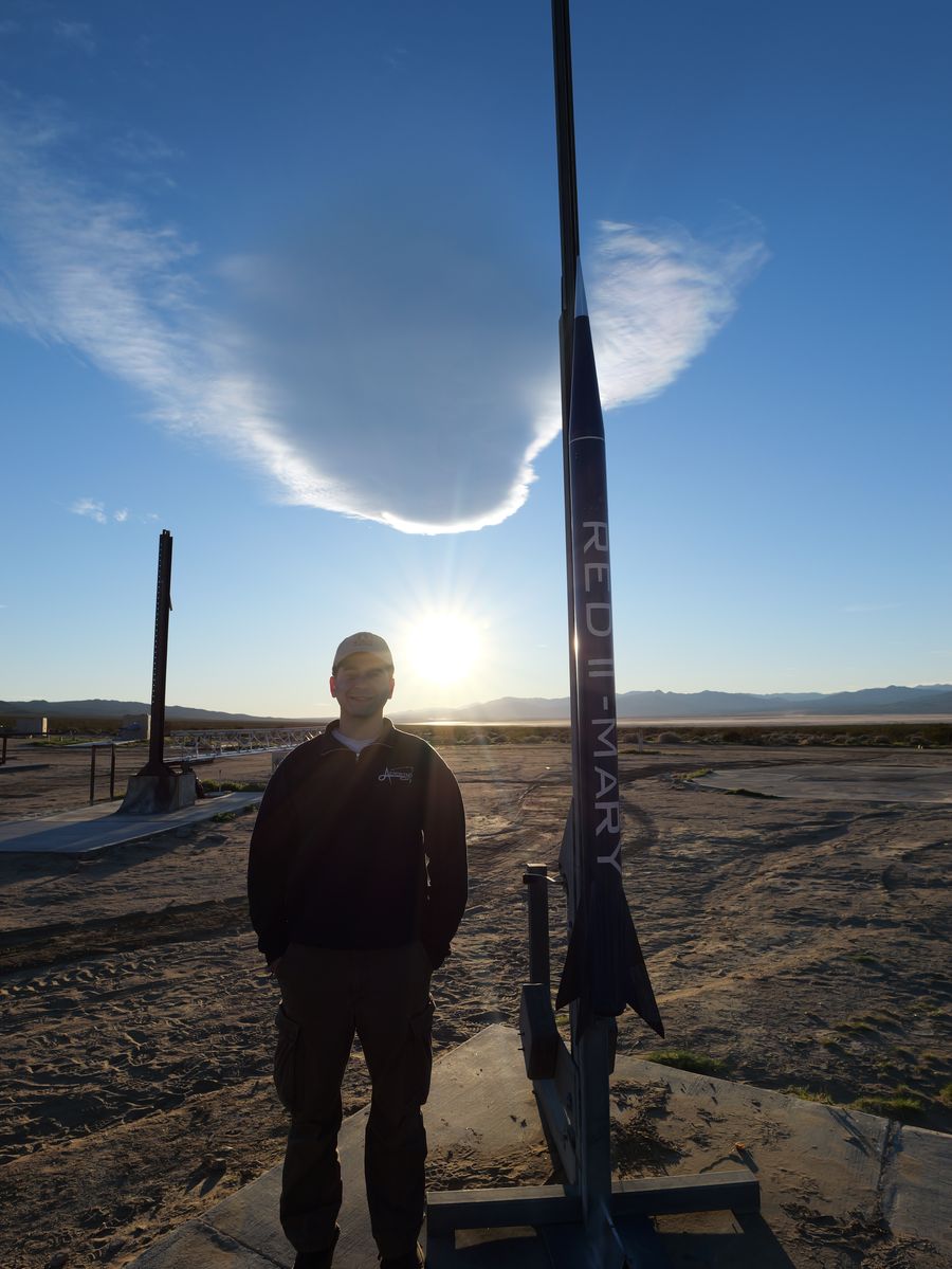
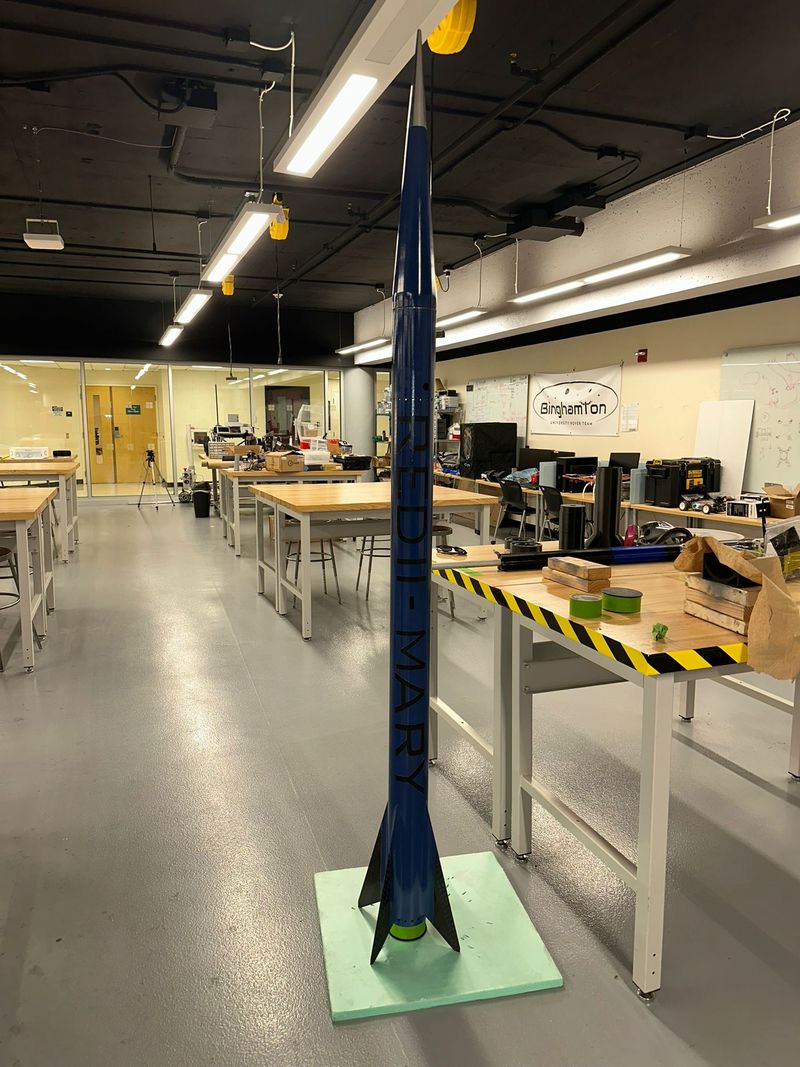
RED II “Mary” on the rail, the morning of the launch.
+ Selected work
External aerodynamics at Mach 3.
External Aerodynamics of Rocket Geometry
ME 541 CFD project / RED 2 “Mary” / ANSYS Fluent and Mechanical
Two questions drove the study: what shock forms around the vehicle and what forces it
puts on the structure, and how you assess aerodynamic performance before flight.
Mach 3
Far-field inlet
18,295,306
Mesh cells
0.992
Avg orthogonal quality
49 m
Spherical far field
Domain and boundary conditions
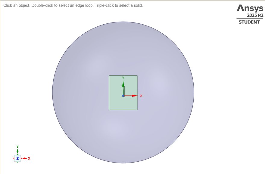
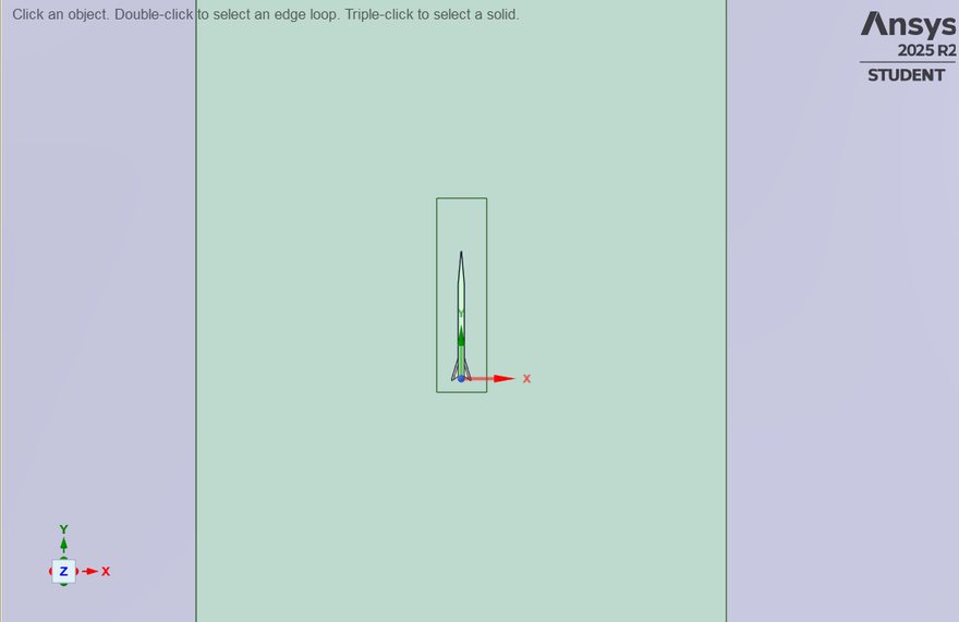
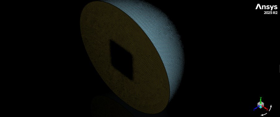
The 2.4 m vehicle sits inside a spherical enclosure 49 m in diameter, roughly
20.4 times the vehicle length. Literature and industry practice suggest about 10x,
but a sphere lets the flow deflect in any direction, which matters once angle of
attack is introduced. The domain is sized to keep the shock properly captured and
the flow from choking, and was increased past the recommendation to avoid meshing
errors.
Inlet
Mach 3, direction-vector far field; outlet inferred
Reference
101,325 Pa atmospheric
Symmetry
Plane cut through the vehicle centerline
Regime
Steady state, compressible
Refinement
Two bodies of influence: 3.6 m first volume, 4.9 m second at 10% of domain diameter
Domain against vehicle. The sphere is 49 m across; the green box is the body of influence and the vehicle inside it is 2.4 m. That ratio is the whole argument for the far-field size.Body of influence. The refinement volume the vehicle sits inside, sized so the shock is captured without meshing the whole sphere finely.
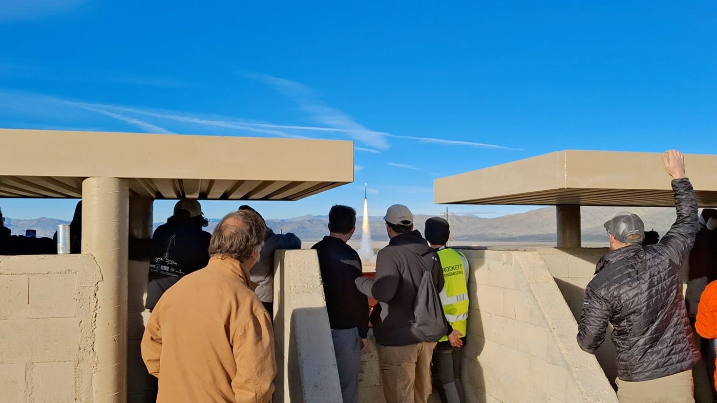
Launch day. The vehicle this study was run for, off the pad.
Meshing strategy
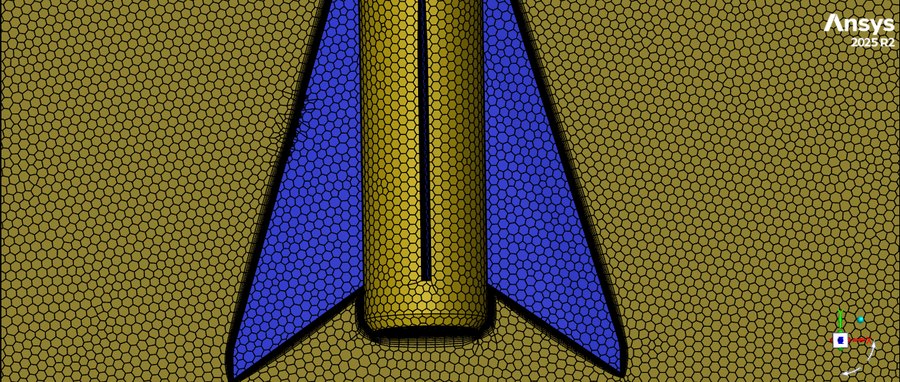
Named selections on the fins, body, nosecone and nosecone tip each carry their own
curvature-based sizing, with the tip and nosecone held to a tighter maximum than the
body and fins. The two bodies of influence are volumes set aside for fine meshing.
Nosecone / tip
0.0001 m local min, 0.005 m max
Body / fins
0.0001 m local min, 0.009 m max
Boundary layer
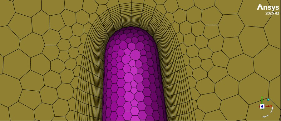
20 layers, last-ratio, 0.0001 m first height
Surface mesh
0.01 to 0.5 m, 3 cells per gap
Volume mesh
Poly-hexcore, 0.0001 to 0.4906 m
Quality
Avg skewness 0.0104, avg orthogonality 0.992
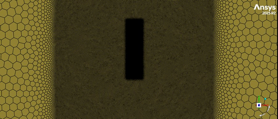
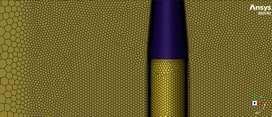
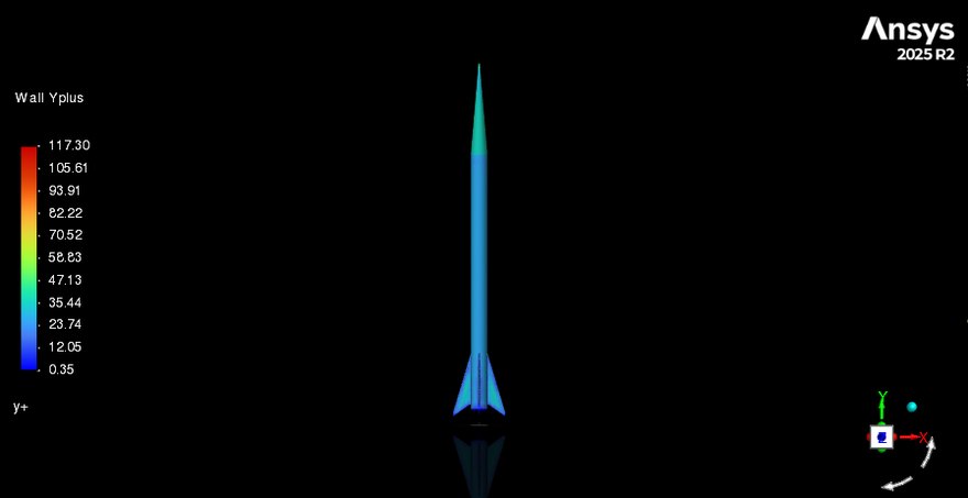
The 49 m spherical far field, cut to show the interior. The vehicle is the small void at the centre, roughly 20.4 times smaller than the domain.Body of influence. Cell size steps down sharply on entering the refinement volume, so resolution is spent where the shock and the vehicle are.Fins, held to a 0.009 m maximum with their own curvature sizing.Body to nosecone transition, where the sizing tightens from 0.009 m to 0.005 m.Nosecone tip. Twenty inflation layers at a 0.0001 m first height, which is what buys the y+ control.Wall y+ on the surface, 0.35 to 117.30, against a 0.0005 m wall-spacing target from a flat-plate estimate.
Numerical method
k-omega SST, chosen for adverse pressure gradients and shock capture in aerospace external flow.
Density-based solver, per ANSYS guidance for high-speed compressible external flow and shock resolution.
Ideal gas law, since density is not constant in compressible flow.
Sutherland equation for temperature-dependent viscosity across the field.
Courant number 1 at startup to prevent divergence, below the 5 to 10 ANSYS suggests, traded for stability.
Convergence monitors
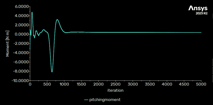
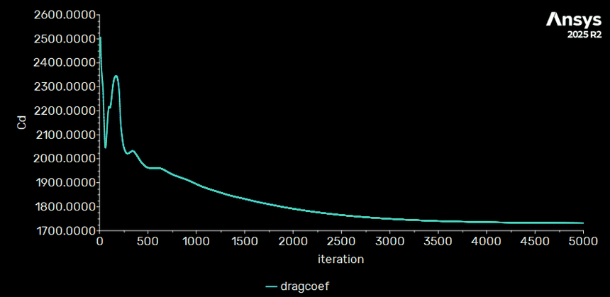
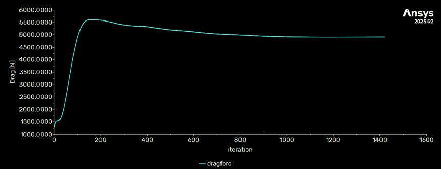
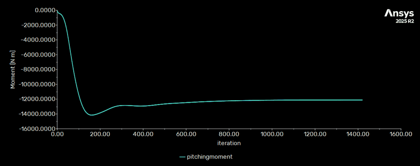
Residuals alone do not prove a converged aerodynamic answer, so drag, pitching moment
and drag coefficient were monitored as integrated quantities. Two cases were run, at
zero incidence and at 15 degrees angle of attack, and reading them side by side is what
makes the force numbers make sense.
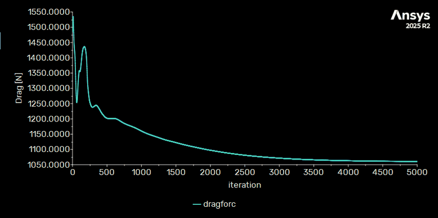
Case 1: no angle of attack
Drag settles near 1060 N on the half model over 5000 iterations. This is the case the RASAero comparison uses.Pitching moment rings down and holds at roughly 0.4 N·m, effectively zero. That is what a symmetric vehicle at zero incidence should give, and it is the check that the case is set up right.Drag coefficient settles near 1730, which is wrong by inspection. The force is right and the coefficient is not, so the reference values were never set for this run.
Case 2: 15 degree angle of attack
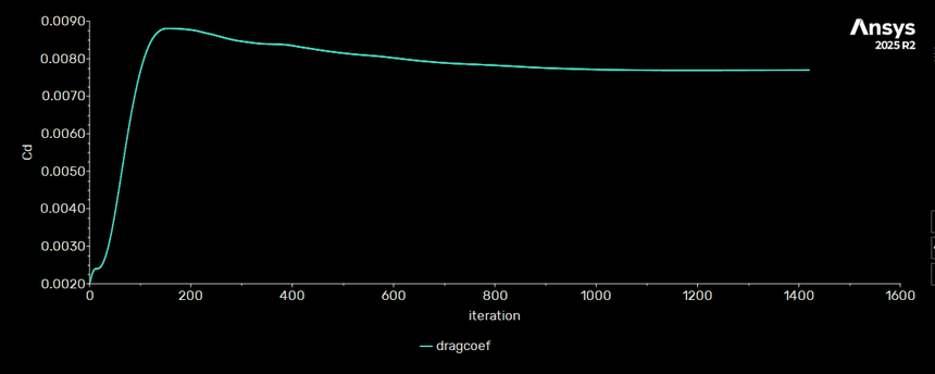
Drag overshoots to about 5600 N near iteration 150, then settles near 4900 N, against roughly 1060 N for the same half model at zero incidence.Pitching moment undershoots to about -14,100 N·m and holds near -12,190 N·m. Putting the vehicle at incidence is what generates it, and it is the load the fins and airframe have to carry.Drag coefficient settles at 0.0077, a physically sensible value. Reference values were set correctly here.
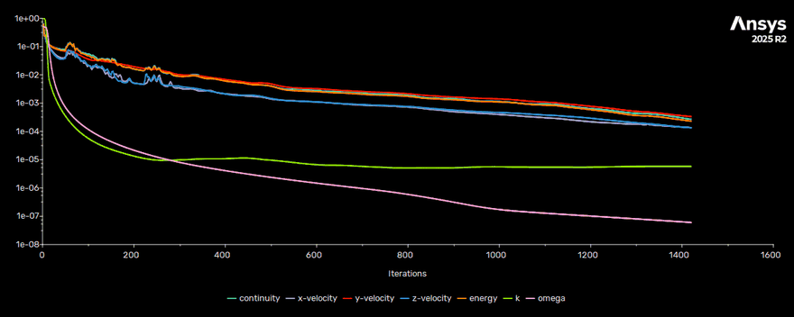
Scaled residuals for this case, falling steadily through 1420 iterations, with omega below 1e-7 and k flat near 6e-6.
Field results
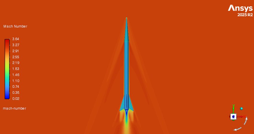
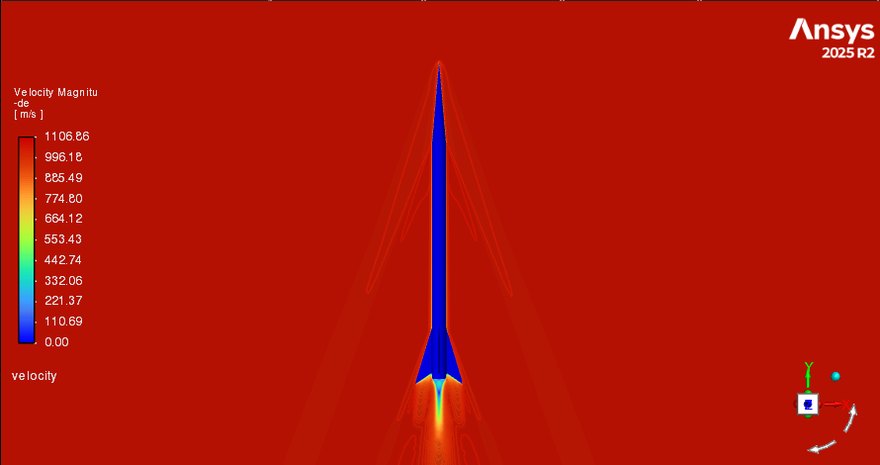
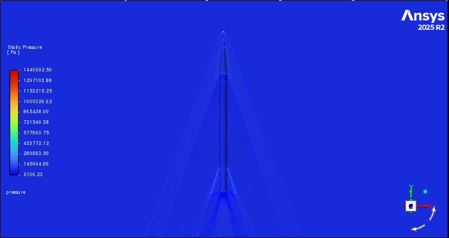
Mach number, scale 0.02 to 3.64. The shock leaves the nosecone and runs back to meet the fins, with the expansion behind the fin can clearly resolved.Velocity magnitude, 0 to 1106.86 m/s. The boundary layer reads as the dark sheath along the body.Static pressure, 2.11e3 to 1.44e6 Pa. The stagnation value at the tip sets the scale, which flattens the rest of the field.
Velocity magnitude as the solution develops. Fluent rescales the colour bar each frame, so the background shifts while the shock structure settles.
Fluid to structure
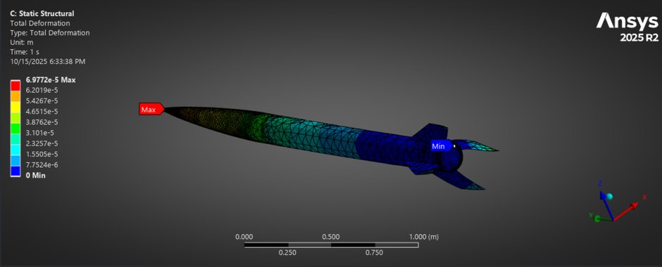
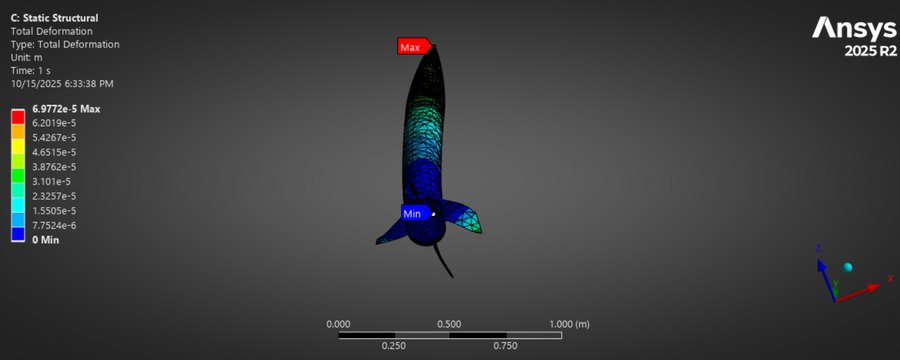
The pressure field was imported from Fluent into ANSYS Mechanical for a one-way FSI
pass on an aluminium structure, symmetry boundary retained and a fixed support at the
base, solving for stress, strain and total deformation. Deflection came out small.
Total deformation, side view. Maximum 6.9772e-5 m at the nosecone tip, minimum at the fin can. That is about 0.07 mm, which is what “deflection came out small” actually means.Total deformation, looking down the body axis, same 0 to 6.9772e-5 m scale.
Verification
The simulation runs on half the rocket, split on the symmetry plane,
so the force it reports is half the force on the whole vehicle. Any comparison against
a full-vehicle hand calculation has to account for that before the two numbers mean
anything.
RASAero II
418 lb, 1858 N, full vehicle
Expected half
929 N across the symmetry plane
CFD, Case 1
1075 N on the half model, monitor settling near 1060 N
Doubled
2150 N, or 483 lb, full vehicle
Two independent methods, roughly 15% apart, which is a reasonable place to be for a
low-order tool against a RANS solve on a vehicle this slender.
Conclusions
Shock formation came as expected, with visible shock interaction as the flow reaches
the end of the nosecone and then on to the fins. Deflection is relatively small.
Limitations and future work
Case 1 reports a drag coefficient near 1730 while Case 2 reports 0.0077 on the
same geometry. The forces are fine in both; the reference values behind the
coefficient were only set in one of them. It is recorded here rather than quietly
dropped, because the monitor that catches it is the same one that proves the force
converged.
Field contours and mesh views come from successive exports as the setup was
refined, so scale maxima differ slightly between figures.
Shrink the far field.
Run it transient rather than steady state.
Move from one-way to two-way fluid-structure interaction.
Add parameter sets.
Microfluidics, hydrokinetic turbines, and drone-based detection.
University at Buffalo Summer Research Conference, 2025.
Weaving-flow micromixer for higher mixing efficiency
Research Assistant, McNair Summer Intern / Lead: Prof. Jifu Tan / June - August 2025
Mixing at low Reynolds numbers is laminar, so the geometry has to do the work. The
question was how far a 30° barrier angle gets you within 450 µm.
Read the methodClose
Built a 3D transient multiphysics simulation in MOOSE, the open-source
C++ finite element framework, modelling laminar microfluidic mixing through passive
scalar transport.
Evaluated density, viscosity, diffusivity and wall-temperature effects at low
Reynolds numbers for lab-on-a-chip systems.
Automated mesh generation, boundary conditions, solver configuration and
post-processing so geometry revisions did not each cost a manual rebuild.
Benchmarked against published HVW literature and matched
89.9% mixing efficiency at Re = 5 within 450 µm for a 30°
barrier angle.
Presented methodology, validation and modelling limitations to
300+ scholars and faculty at the University at Buffalo Summer
Research Conference.
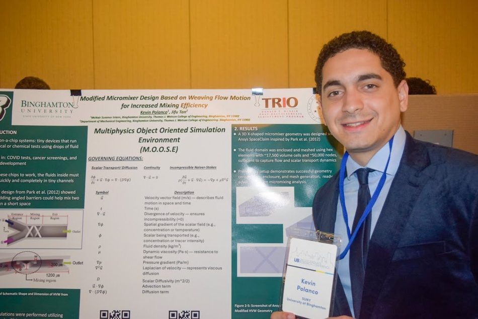
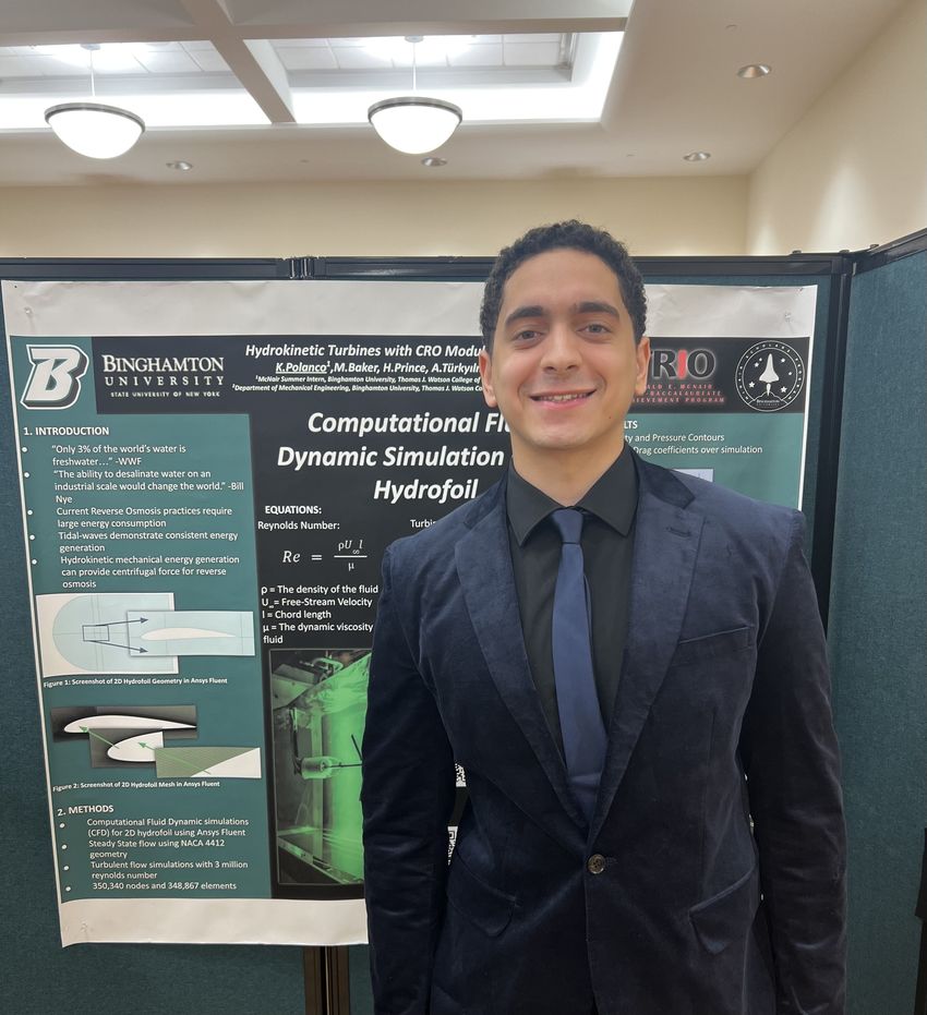
The poster carries the governing scalar transport, continuity and incompressible
Navier-Stokes equations, alongside the meshed 3D X-shaped micromixer geometry.
Hydrokinetic Turbines with CRO Module, McNair Scholars poster.
Desalination using hydrokinetic turbines with a CRO module
Research Assistant, McNair Summer Intern / Lead: Prof. Cosan Daskiran / June - July 2024
A feasibility study of a hydrokinetic turbine driving centrifugal reverse osmosis,
where the blade profile is the variable under test.
Read the methodClose
Modelled the turbine and centrifugal reverse osmosis concept using
Blade Element Momentum and Blade Element Theory, quantifying expected
turbine performance to support feasibility analysis and design limitations.
Validated blade profile selection with high-order CFD measured against BET/BEM,
running 15 turbulent ANSYS Fluent cases across 3 NACA profiles.
Presented to 50+ faculty and research participants, documenting
constraints and tradeoffs in a poster and technical briefings.
Work with M. Baker, H. Prince and A. Türkyılmaz. The 2D NACA 4412 hydrofoil
case ran at Re = 3 million on 350,340 nodes and 348,867 elements.
Drones with hyperspectral imaging and LiDAR to locate unexploded ordnance
Team Lead / Binghamton University / August 2021 - December 2022
Twenty-six inert munitions laid out on a known grid, so that each sensor could be
judged on what it actually detected against the environment.
Read the methodClose
Led a 6-person field campaign for UAS-based UXO detection across a
400 m × 400 m site, integrating GPR, hyperspectral imaging, LiDAR
and ArcGIS analysis.
Planned a controlled layout of 26 inert munitions: 3 MBRL,
2 TM-62 anti-tank, 3 VPMA-3 and 18 PFM-1 anti-personnel.
Evaluated sensor-specific detection strengths against the environment rather than
treating the sensor suite as one instrument.
Presented findings at the European Geosciences Union conference,
attended by 14,000+ participants.
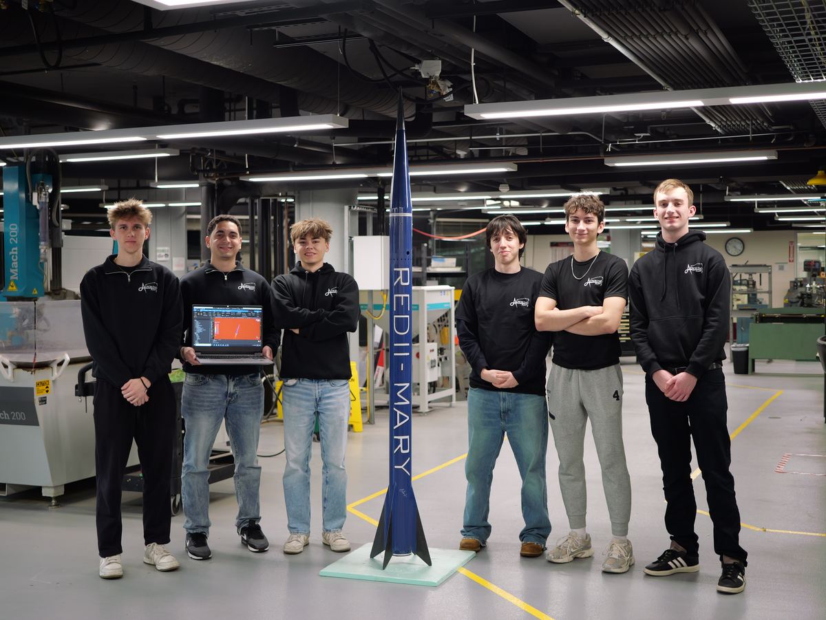
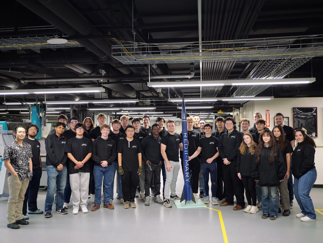
Eight engineers, one set of simulation standards.
AeroBing Rocketry. Velocity pathlines behind the club mark.The simulations team, with RED II “Mary” assembled and the Mach field open on the laptop.
AeroBing Rocketry Research Group
Simulations Team Lead, Aug 2025 - May 2026 / Member Aug 2022 - Aug 2025
Eight undergraduate engineers running CFD and FEA in parallel on one shared server,
against one set of standards, so that a design decision made in simulation actually
holds up in fabrication.
Read the methodClose
Owned end-to-end external aerodynamics analysis for student launch vehicles,
leading 8 undergraduate engineers running parallel CFD and FEA studies
on a shared remote desktop server.
Evaluated compressible turbulent flow, RANS and LES, in ANSYS Fluent
to assess y+ control, time-step convergence and aeroelastic deformation risk before
fabrication.
Set team simulation standards covering meshing convergence, simulation accuracy and
hand-calculation verification, and oversaw projects for future vehicles across
multiple concurrent subteams.
Designed the carbon fiber fins for RED 2 “Mary”, iterating
geometry from low-order calculations in RASAero II and AeroFinSim, high-order work in
MATLAB, and coupled FSI from Fluent into Mechanical, for a
35% increase in stability margin.
Static fire
Motor static fire on the test stand.
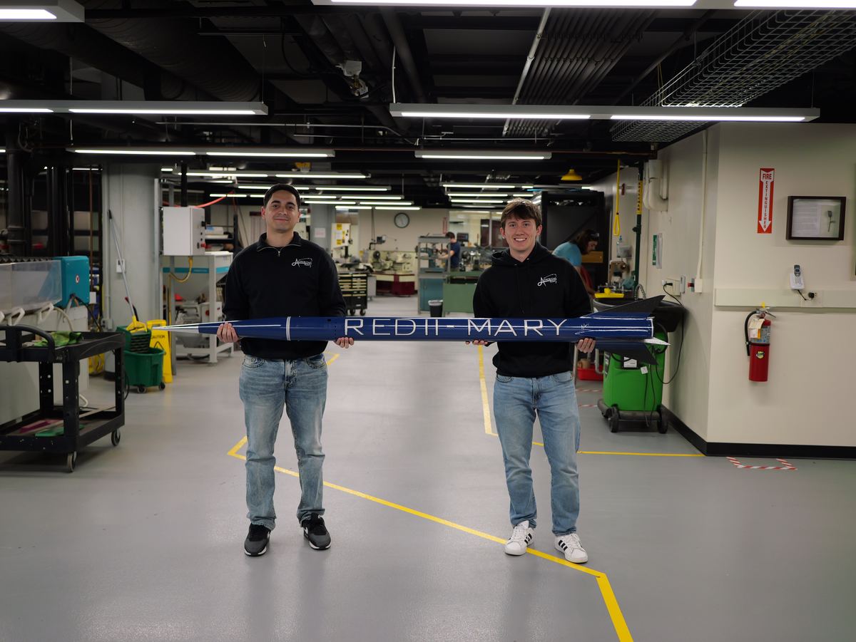
The airframe out of the rack, nose cone to fin can.RED II “Mary” on the stand, finished.
AeroBing Rocketry Research Group. The simulations team is one of several concurrent subteams.
+ Coursework
Two design projects, one built and one simulated.
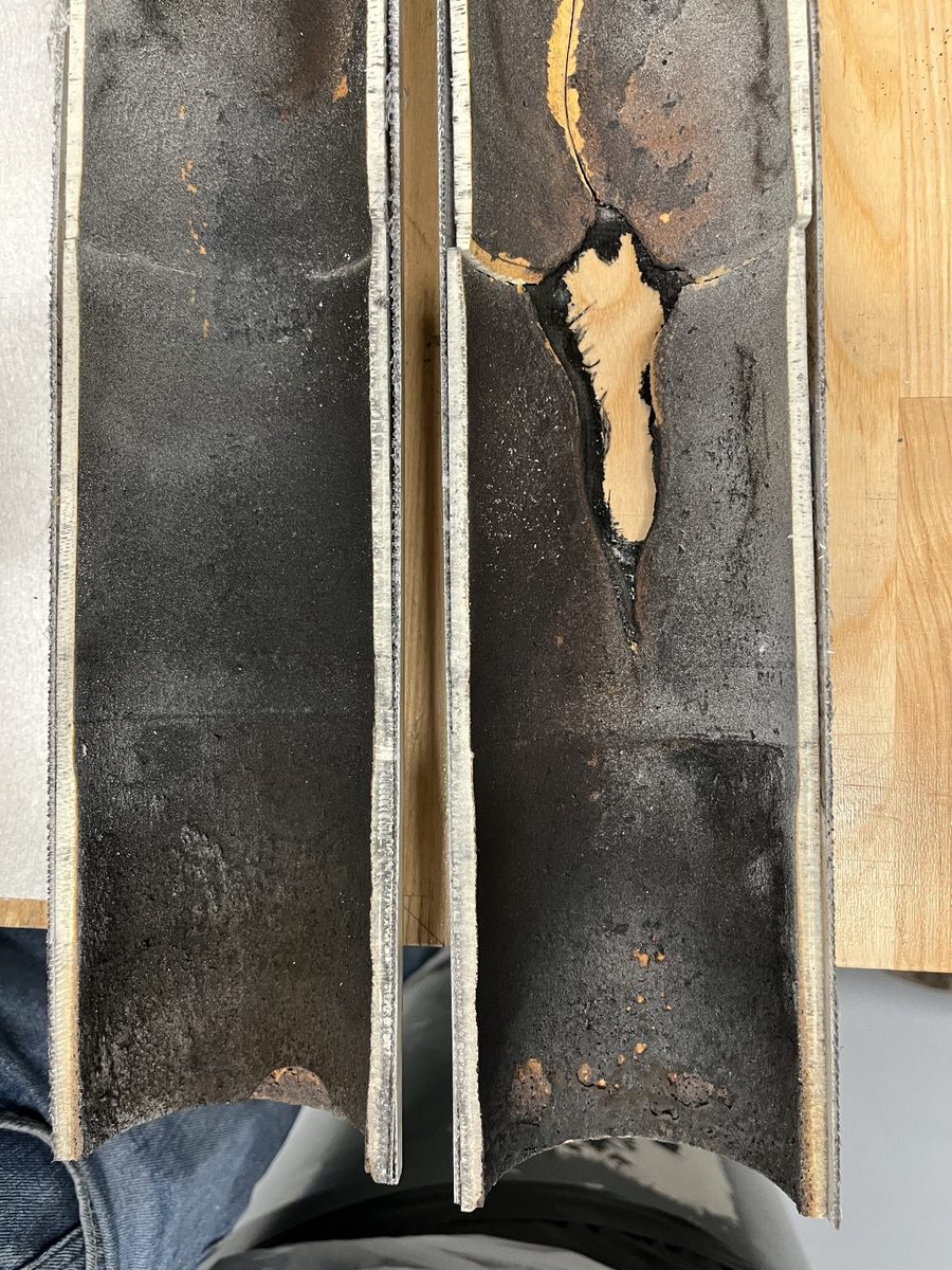
What an uncharacterised liner looks like after a burn.
Insulation characterization apparatus
ME SDP 124 / Secretary, FEA and instrumentation / Aug 2025 - May 2026
AeroBing builds its rockets from scratch and insulates them with HTPB liner, but the
liner has never been characterised. So the margin against burn-through is guesswork.
This apparatus measures its thermal conductivity.
Read the methodClose
Why it matters
If the liner fails, hot gases escape through the insulation and burn through, and an
extreme burn-through takes the casing with it. The famous case is the Challenger SRB
joint: same physics, different scale. Design margin against that requires knowing the
liner’s thermal conductivity, and until now it was tested iteratively per rocket
rather than characterised once.
Target
Measurand
Thermal conductivity k, roughly 0.2 to 0.4 W/m·K, under a controlled ΔT
Sensitivity
Down to 0.2 W/mK, tolerance 0.1 W/mK
Method
Heat flow meter, ASTM C518
Reference
Phenolic sample of known conductivity, for transducer calibration
Why a heat flow meter
Fully standardised under ASTM C518, with documentation and proven
repeatability.
Works on elastomeric samples like HTPB liner, which probe-based transient methods
do not.
Builds from accessible materials, aluminium plates and steel supports, and is
straightforward to fabricate with available machining.
Guarded hot plate, cut bar, transient hot wire and transient line source were all
considered and eliminated on manufacturing constraints, budget, documentation, or
measurement error on this sample material.
The stack
A sandwich configuration, modular so parts swap out, with tuned sample compression.
Eight thermoelectric coolers, four above and four below, hold the plates near
isothermal and set a one-dimensional gradient. A heat flux transducer in the stack
outputs a voltage proportional to the through-thickness heat flow, and the metered
region keeps convection and edge losses negligible.
Exploded assembly. Cold plate heat sink, cold plate with TECs, phenolic sample, hot plate with the heat flux transducer, hot plate heat sink, alignment dowels, and the base plate with its fan.
My part
Ran ANSYS Mechanical FEA with hand calculations to verify support
stress, deflection, buckling resistance and manufacturability before fabrication.
Resolved instrumentation and thermal control limits by implementing
PWM controllers and a 16-bit LabJack U6 DAQ for microvolt-level
thermopile signals, with RTDs logging plate and sample face temperatures.
Wired, soldered, troubleshot and validated the Peltier sensor system against the
phenolic reference.
Coordinated a $1.5K build across AeroBing, faculty and the Watson
Fabrication Lab, sourcing components and tracking orders, returns, schedules and
requirements.
Authored major portions of the 50-page report and the design review
presentations through prototype handoff.
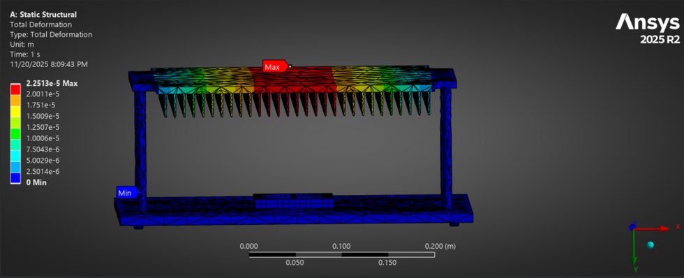
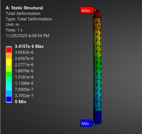
Apparatus deformation under load, maximum 2.2010e-4 m across the plate stack and supports.Alignment dowel, maximum 3.4157e-6 m. Four steel dowels carry support and alignment, bolted to the base plate and press-fit into the bottom heat sink.
Team
Aleksander Skrodzki, team lead. Kevin Polanco, secretary. Sam Rossberg, procurement.
Julian Hu, finance. Faculty advisor Dr. Chiarot, sponsor Malcolm John.
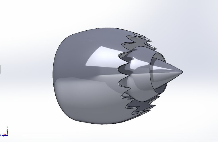
Chevron nacelle, serrated trailing edge.
Commercialization of supersonic flight: turbofan CFD
Junior design / Individual project / Jan - May 2025
Baseline against chevron nacelle on a Trent 1000 at 35,000 ft. On exit-plane RMS
pressure the two came out 0.1 dB apart.
Read the methodClose
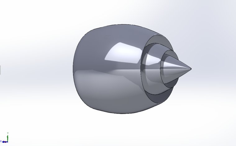
Developed baseline and chevron nacelle geometries for a
Rolls-Royce Trent 1000 in SOLIDWORKS.
Constructed a 15 m far-field CFD domain with near-wall and
shock-region mesh refinement.
Ran compressible SST k-omega RANS simulations across inlet-angle
sweeps at 35,000 ft, comparing drag and exit-plane pressure and velocity trends.
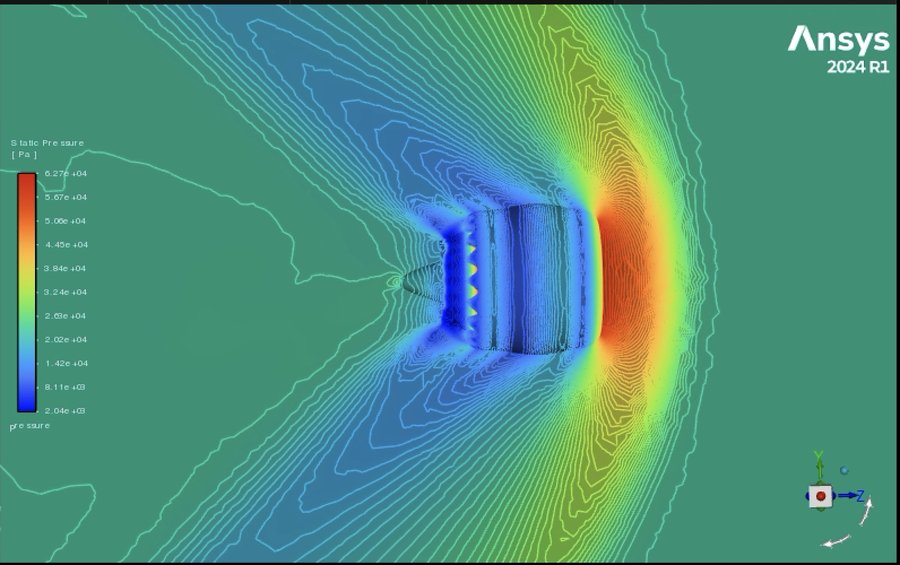
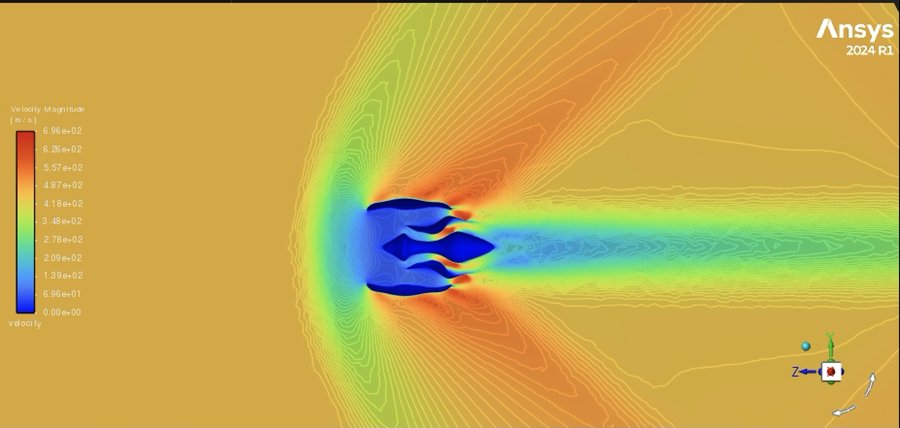
Estimated acoustic performance from exit-plane RMS pressure:
181.4 dB baseline against 181.5 dB chevron.
Documented methodology, verification and fidelity limitations in a 21-page report.
Geometry and field results
Baseline nacelle, plain trailing edge. Everything else held constant.Static pressure, 2.04e3 to 6.27e4 Pa. The chevron scallops are resolved individually at the trailing edge.Velocity magnitude, 0 to 696 m/s, with the exhaust jet running downstream to the exit plane where the acoustic estimate was taken.
Built for the fun of it.
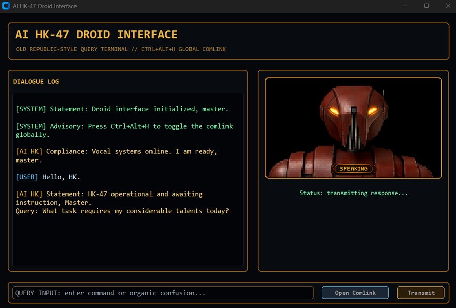
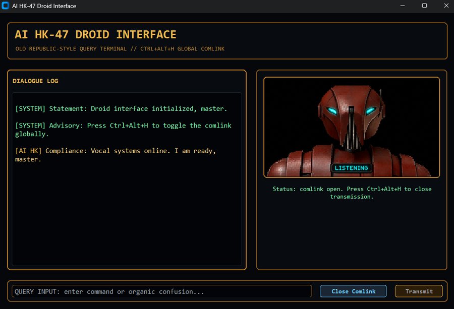
AI HK, end to end. Idle, a request typed in, and the reply drafted and spoken back. Sound on the clip.
AI HK
Windows desktop voice assistant / Python
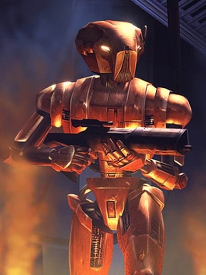
A voice assistant styled after HK-47 from Knights of the Old Republic, sitting on a
global hotkey.
Read moreClose
CustomTkinter for the interface, with image states for idle,
thinking and speaking, a ready cue and a shutdown protocol.
OpenAI Responses API behind it, with real-time web search.
ElevenLabs for the voice, sounddevice for mic
input and pynput for a global Ctrl+Alt+H hotkey.
The interesting problem was barge-in. Hitting the hotkey mid-sentence has to cut
the audio immediately and reopen the mic, without the previous response talking
over the new one. Solved with response-epoch protection.
Front Desk Supervisor, Aug 2024 - May 2026 / Front Desk Manager, Aug 2022 - Aug 2024
First point of contact for the office: phones, email, scheduling, and the EOP/SSS
library, for four years running alongside everything above.
See moreClose
First point of contact for students, staff, faculty and visiting families,
managing all incoming phone and email for the office.
Promoted to Supervisor after two years; took over building the front desk
schedule and coordinating daily coverage.
Managed study room reservations in Skedda and circulation for
the EOP/SSS library, tracking checkouts and keeping the space organized.
Answered day-to-day questions on course scheduling and degree requirements, and
referred students to the right office.
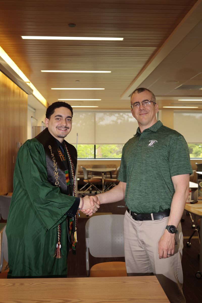
Signing off with Ryan Mead, Assistant Director of Academic Support Services and Programming at Binghamton EOP.
Also with EOP, Binghamton Enrichment Program
Academic Coach
June - July 2024Outreach to 50 to 70 incoming EOP students, with a recurring caseload of about 35. Coached study skills, time management and academic habits, concurrent with a full-time McNair research position.
Study Hall Facilitator
June - July 2025Supervised study halls of up to 30 incoming freshmen across multiple locations, enforcing study hall policy and quiet hours, concurrent with a full-time McNair research position.
Also worked
Whole Foods Market
Summer & Winter 2023Prepared Foods Team Member, New York, NY. Ran the chef case, slicing and packaging meats and cheeses to order.
Shake Shack
Summer & Winter 2022Team Member & Cashier, New York, NY. Register, shake station, fryer and grill as volume required.